Loading...
 

Electronics

This blog described electronic components that can be used to support or interface to nanodevices.

Open Hardware Summit 2022

morreale Thursday 11 of August, 2022

The Open Hardware Summit was held on April, 22, 2022 online with ~19 speakers from working on project around the world. Recordings of the talk can be found on YouTube and tweets about the summit can be found @ohsummit. Open Hardware Summit 2022 Schedule

2022 Summit Team

The organizers of the summit did a fantastic job and included Lee Wilkins, Claire Cassidy, Sid Drmay, Nadya Peek, and Alicia Gibb.

Open Hardware Summit 2022 Organizers

Summit Talks

My list of links and brief talk summary for each talk follows.

A Few Tools for Re-Imagining the Future

Ashley Jan Lewis

  • Afrofuturism of the Science fiction writer Octavia E Butler
  • Octavia E Butler wrote the Parable of the Sower book series which predicted our current situation
  • Octavia Rules from predicting the future.
    • Learn from the past
    • Respect the law of consequence
    • Be aware of you perspective
    • Count on surprises
  • Predicting the future can be used to avoid hazards
  • Slimtech Labs

A Better Hardware Life Cycle: Build Stuff Without Feeling Like a Jerk

Alex Glow

How Frustration Led to Delft Open Hardware

Jerry De Vos

Open Source Tools for Making Open Source Hardware

Leon Anavi

Community-Led Distributed Manufacturing

Vaibhav Chhabra

Material Testing Procedure: How to Recycle All Kinds of Waste Plastic Via Pellet 3D Printing

Hellen Little

FluigiCAD – Building open source CAD tools to make microfluidics more accessible

Radhakrishna Sanka

Open Source Hardware for Science, in the Context of Public Policy

Alison Parker

Introducing an Open Systems Assembly Protocol, or, a proposal regarding how to build OSHW’s modular, networked future.

Jake Read

Question Everything: How we Shipped an Open Hardware Laptop by Breaking all the Rules

Lukas F Hartmann

  • MNT Reform
  • 3D print replacement parts in PLA
  • $LiFePO_4$ batteries in standard size because they are safer
  • Works in batches of 100 normally, but 50 batches for the laptops. Updated from batch to batch
  • KiCad

How the Open Hardware Observatory (OHO) can help publish hardware

Robert Miles

Equity-Driven Design

Dr. Alexander Adams

Open Source Toys for Endangered Animals

Andy Quitmeyer

How to Enable Anyone to Build their Own Renewable Energy System

Kathrin Weihe & Michel Langhammer

Knotty (Naughty) Hardware

Anuradha Reddy

Can Pretty Antennas be Practical? Designing cuteformal antennas for WiFi/Bluetooth integration

Christin Lundgren

Panel on Open Hardware and Health Tech

with Robert Viseur, Bérengère Fally, Samuel McDermott, and Robert L. Read

Berengere Fally

Samuel McDermott

Robert Read

Panel Discussion

Links


Learn electronics and programming from Arduino Education, Raspberry Pi Foundation, Lego Education, and tinyML

morreale Tuesday 15 of June, 2021

Learn electronics and programming from Arduino Education, the Raspberry Pi Foundation, Lego Education, and tinyML with kits, courses and teacher resources. Arduino Education offers STREAM program for students in middle school through college. The Raspberry Pi Foundation has hundreds of hours of lesson plans to teach programming. Lego Education has kits and lessons to teach young children about mechanics, coding, and electronics. tinyML has been developing courses on edX to teach machine learning on low power devices. A list of the resources is shown below.

Arduino UNO, MKR WiFi 1010, VIDOR 4000, Protenta H7 & camera, Raspberry PI 4B, Pico RP2040 and sensors

Arduino Education

Student Kits

Explore IoT Kits

Engineering Kits

Kits

Raspberry Pi Foundation

LEGO Mindstorms & Spike Prime

  • The Lego education makes the Lego Mindstorms Education sets.
  • The past NXT version used Labview to program the NXT controller.
  • The Lego Mindstorms EV3 Core set version looks like it uses Python now.
    • The EV3 is to be retired on June 30, 2021, and will be supported for 2 years. The EV3 is to be replaced with SPIKE Prime.
  • SPIKE Prime comes with educational courses and teacher resources too.

tinyML


Open Hardware Summit 2021

morreale Sunday 11 of April, 2021

The Open Hardware Summit 2021 was held as a virtual meeting again this year on April 9, 2021. The event platform, Hopin, was used instead of Discord and YouTube live. It worked well for the event stage and provided venues for vendors in a virtual expo setting. It was a little harder to follow chats for each talk without opening multiple windows.

The Open Hardware community appears to be doing well even in the pandemic with the number of talks, the enthusiasm of the participants, and number of sponsors. The recording can be seen on YouTube. There were ~17 talks on the schedule and my list of links and brief talk summary for each talk follows.

COVID 3D TRUST: a public-private collaboration to support manufacture of open source PPE and medical devices during the COVID-19 public health emergency

Meghan McCarthy

reGOSH: appropriating technology in Latin America with open science hardware

Julieta Arancio

Open Hardware Makers mentorship program: making open hardware the default everywhere, one project at a time!

Andre Maia Chagas

  • This is a open hardware mentorship program sharing best practices based on the Mozilla Open Leaders development program. The program runs 15 weeks and matches the project to a mentor with weekly calls and assessments.
  • Open Hardware Spaces
  • OSHW Weather Report
  • OHM Slides

Mobilizing People to Act on Air Pollution with the Bucket Air Monitor - a Community Science Tool

Rico Euripidou, Katie Gradowski

Hardware innovation, an opensource way in Nigeria

Oluwatobi Oyinlola

  • Open source ventilator
  • DIY Solar Panel
  • PPE Compliance
  • SolarPocha

Open Hardware Needs Open Standards

Chris Chronopoulos

Interface Design in Open Source Hardware and Software

Scott Shawcroft

  • Scott recommends that open hardware developers start with the code or description of the board and interface first before designing the board specifications and requirements.
  • @tannewt
  • Circuit Python
  • Feather Wing GitHub repository

Twirling Tech Goddess Q&A

LeeLee James

  • Alicia interviewed LeeLee about creating an inclusive and diverse tech channel for under represented people on YouTube.
  • Twirling Tech Goddess

How Open Hardware Supported the COVID19 Response and Lessons for Public Policy

Alison Parker, Alex Long

Transitioning an Open Hardware Project to Distributed Medical Device Production

Julian Stirling

Breadwinner

Fred Benenson

  • Bread making goes back to Egypt 4500 year ago.
  • Sourdough contains both a yeast and a bacteria. Yeast leavens the bread and the bacteria give the bread the favor. The two live in a symbiotic relationship.
  • Fred built a starter monitor to alert baker when the starter is ripe that contains a Time of Flight sensor that fits on a wide mouth mason jar.
  • Breadwinner community
  • breadwinner-life / community-hardware

What's the Buzz About?: The Rise of Open, Personal Sex Tech

Laura Lytle, Alice Stewart

  • nogasm
  • Lovense
  • Vibio toys
  • Lora DiCarlo
  • Hacking tech and pleasure
  • butplugs open source hardware
  • Kinky Makers Community
  • Open source sex training
  • Deep throat trainer
  • Silicone Molding for Product Design

Robot unicorns, moon cello gloves and open technology

Helen Leigh

  • The Glove Kit was produced in two batched with 3000 kits in a first production run and ~5000 kits in a second run and used to teach kids electronics and making. It also led to working with a musician who used the Glove in an unexpected way control the music as part of her musical performance.
  • Self taught electronics developer now at Crowd Supply working creators on their product development.
  • @helenleigh
  • @crowd_supply
  • emby-emby
  • Open UK
  • The Fomu: An FPGA That Fits in Your USB Port
  • Pimoroni MINI.MU Glove Kit - without micro:bit

Open hardware chip design panel

Megan Wachs, Drew Fustini, Mohamed Kassem, bunnie, ​ Jason Kridner

A Hyena Ate My Project! - Open Source Hardware in Wildlife Conservation Technology

Akiba Jacinta Plucinski

  • International environmental monitoring
  • Prevent sewage dumping into Nile river
  • Camera traps to monitor and observe wild life behavior
  • Elephant monitor
  • Wild Labs

OpenAir Cyan: Accelerating Carbon Dioxide Removal through Open Hardware

Dahl Winters

  • Cyan is a Direct Air Carbon Capture (DACC) prototype designed to remove carbon from the air using hydrated Lime, water, a fan, and an aquarium pump. Cyan converts CO2 to Calcium Carbonate, can be built in about an hour, and costs about $100 for the parts. The objective of the project is to improve the design so that it removes 1 kg of CO2 per day.
  • openair-collective / openair-cyan
  • OpenAir Collective

Conservation AI: The World's Most Advanced Wildlife Tracker Is Now 100% Open Source

Adam Benzion

  • Raise $150,000 to build a tracker for sponsors
  • Irnas.eu designed and made 10 Elephant trackers collars in 4Q 2020
  • ElephantEdge board
  • OpenCollar
  • Smart Parks

Arduino MKR WiFi 1010 on the Cloud Demo

morreale Tuesday 16 of March, 2021

Introduction

The trusty Arduino desktop IDE has a cloud counter-part that offers similar features, but without the needed to install anything other than a small plugin and a browser. Library and board updates are done automatically. The Arduino Create Web Editor is the cloud version of the IDE, and looks and feels similar to the Arduino desktop IDE. To use the Arduino Create, a cloud compatible board is required which includes the following boards:

  • MKR family boards
  • Nano 33 IoT boards
  • Portenta H7 boards

Arduino Create also supports Linux based devices using the Manager for Linux tool. The supported devices include the following:

  • Arduino Pro Gateway
  • IEI Tank AIoT Dev Kit
  • Raspberry Pi
  • BeagleBone
  • UP Squared AI Vision Kit
  • UP Squared Grove IoT Development Kit
  • Arm based platforms running Debian Linux
  • Intel based Platforms like the Intel NUC and the Gigabyte BRIX.

Account Setup and Things

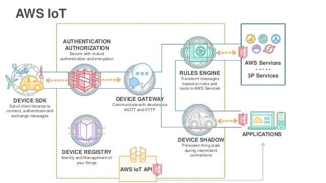
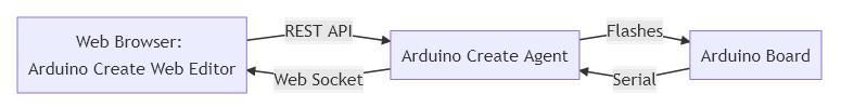
I created my Arduino Create account, and created a new Thing called CloudSense. In the Arduino Cloud, each devices is a Thing which has a unique name and is assigned a unique ID. I installed the small plugin known as the Arduino Create Agent that allows the Arduino Create Editor to detect and communicate with the board to be programmed. I also connected my MKR WiFi 1010 to the cloud. The architecture of the Arduino Create Editor and Agent is shown below.

Arduino Create Block Diagram

During the connection process, the Create Agent erupted with error messages because it could not identify the MKR WiFi 1010 board. It turns out that I also had a Microchip SAM E70 Xplained board, a MPLAPX PICkit 4 debugger, a SAM D20 Xplained board, a Arduino Uno, and a Microchip Curiosity board plugged into the computer via a USB hub as well. The Create Agent does did not seem to be able to determine which board to select. I disconnected all but the MKR WiFi 1010 and the Arduino Agent was able to connect the board to my CloudSense Thing.

Once the device is connected to the Arduino IoT Cloud, the device wireless network connection must be configured. I added my wireless router SSID and password used on a guest network on my wireless router for small devices to keep them isolated my main network until I better understand the security implications of connecting these cloud connected devices to my LAN.

Uploading a Sketch

I uploaded my first sketch from the Create Editor to the board. The sketch is a modified version of the sketch from the prior blog Arduino WiFi 1010 with carrier board and Sensor Demo that was derived from the WiFi RTC tutorial. It was modified to run on the cloud and to use IoT dashboard features. Only the variables defined in the CloudSenes Setup tab can be displayed on the IoT Dashboard, and these variables are automatically defined in thingProperties.h instead of in the main sketch. WiFi network configuration information is stored in the Secret tab. This allows you to share your sketch without divulging your wireless LAN SSID and password.

This examples illustrates how an instrument built with an Arduino can be connected to the cloud to share the measurement status with a large group of interested collaborators. The goal is to share and analyze data from multiple instruments located anywhere in the world. This effort is intended to demonstrate an automated means of controlling, monitoring, and sharing test data for the Direct Air Carbon Capture (DACC) test unit known as Violet being developed by the OpenAir Collective. Data sharing and analysis will be explored in future blogs.

Sensor Connections

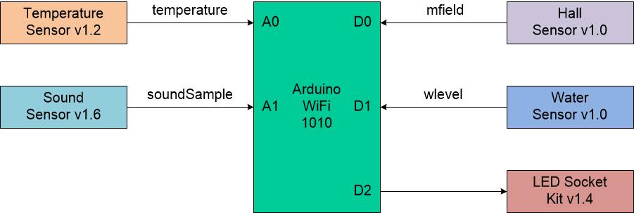
The Arduino WiFi 1010 is connected to four sensors and an LED Socket kit for the CloudSense sketch. I used sensor from the Grove starter kit and sensors I purchased for another project to see how the Arduino Cloud Create works. The sensors and associated variables are as follows.

Arduino Sensor variable Table

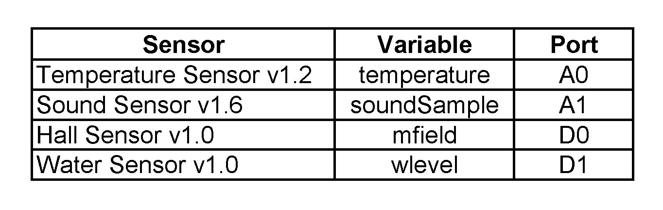
An LED Socket kit is connected to port D2 and is turned on when the sound level is greater than a threshold value. The block diagram of the connections to the Arduino WiFi 1010 is shown below.

Arduino Sensor Connections Block Diagram

I expect to upgrade the configuration with sensor that are more appropriate for the application once they have been determined.

Arduino Create

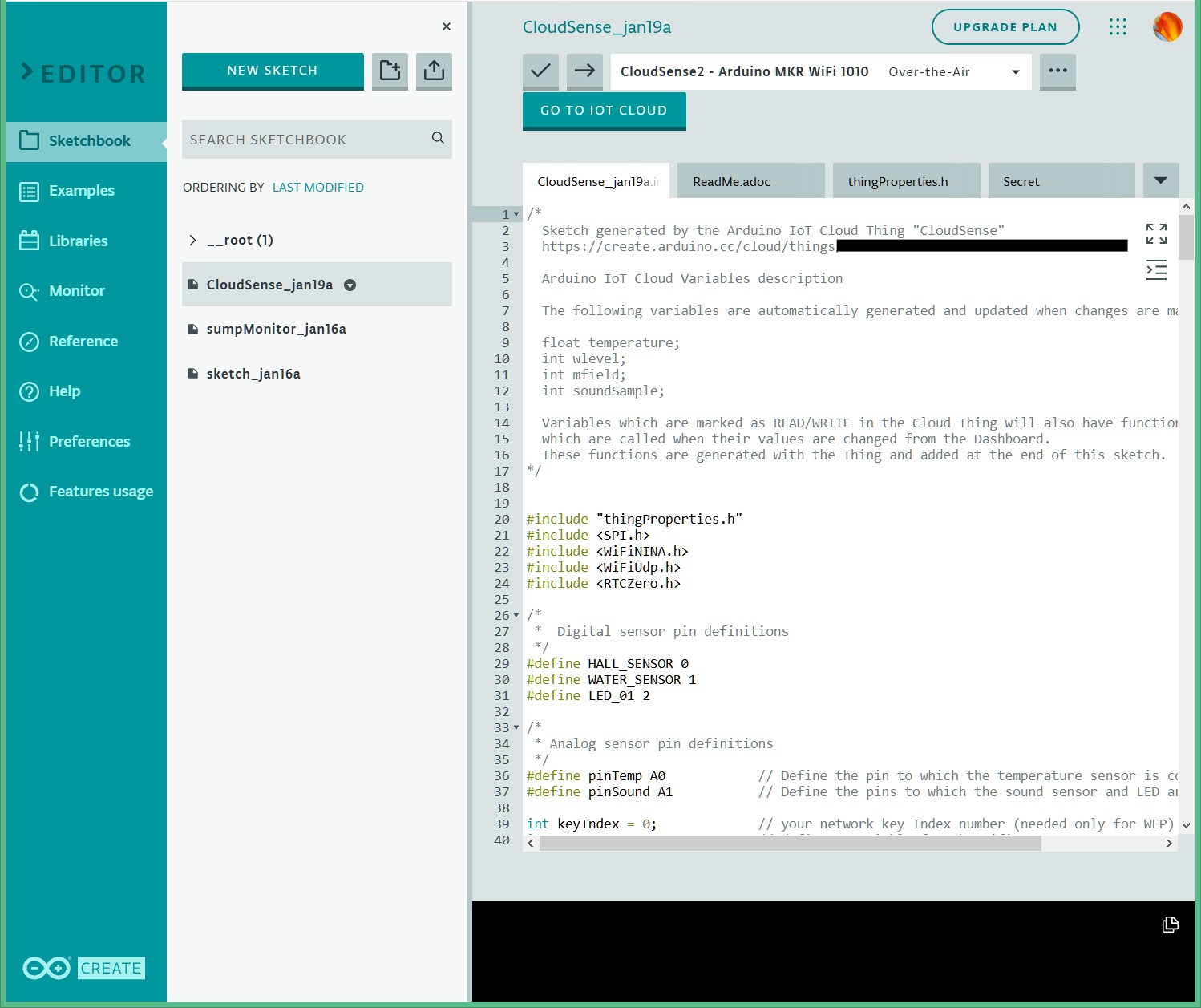
I used Arduino Create to make a new sketch and pasted the Arduino WiFi 1010 with carrier board and Sensor Demo sketch into it. It turns out that it might have been easier to use the import function instead. Arduino Create augmented the CloudSense Sketch name to CloudSense_jan19a. The _jan19a part of the name does not appear in the Arduino IoT Cloud setup.

Arduino Create Sketch

Connecting Things to the Cloud

I used the GO TO IOT CLOUD button to setup variables to display on the Dashboard tab.

Setup

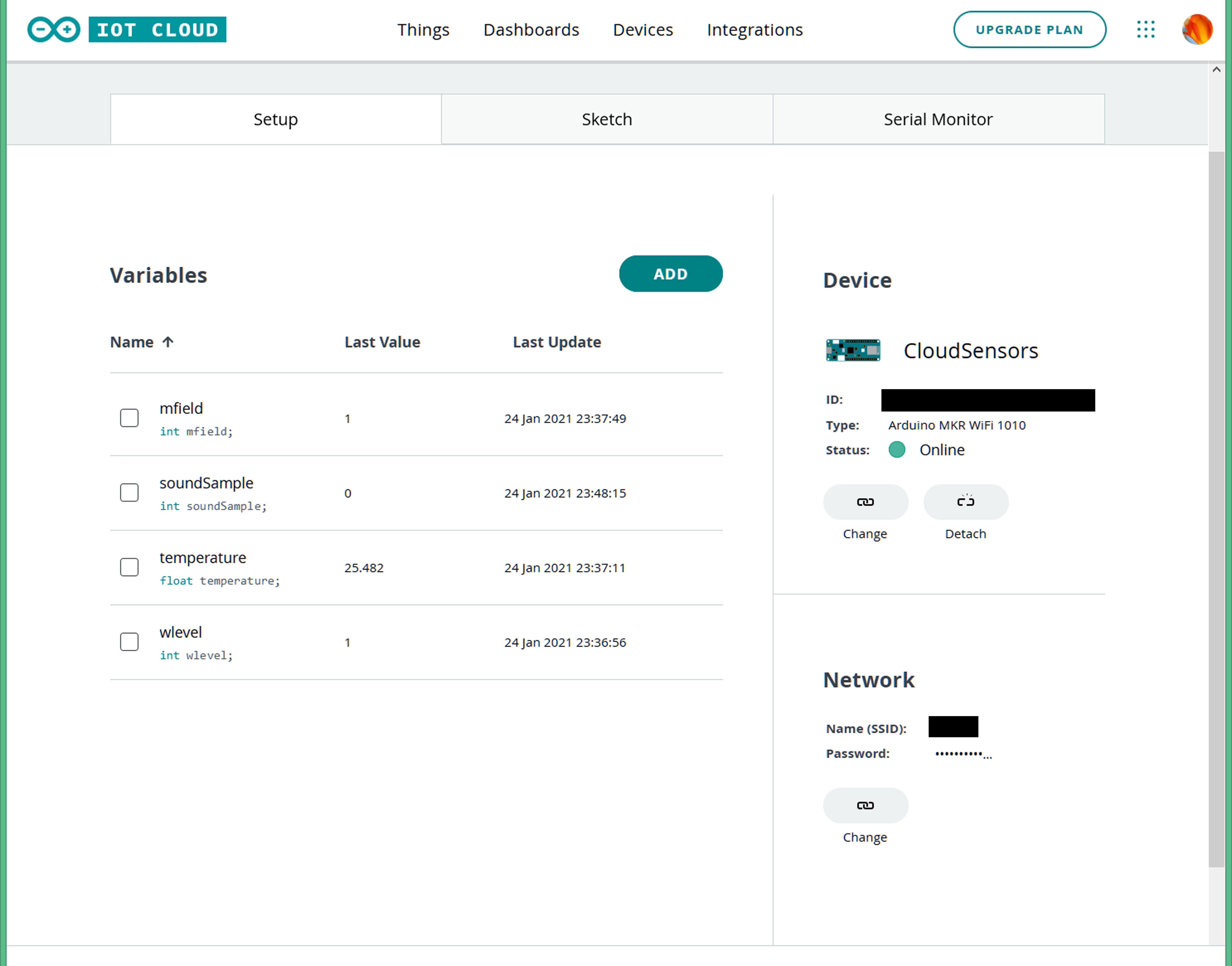
The following four variables were defined so they could be displaced on the Dashboard. These include the following variables:

  • mfield: An int variable for state of the magnetic Hall sensor
  • soundSample: An int variable for the sound sample level
  • temperature: A float variable with the calculated value of the temperature
  • wlevel: An int variable with the state of the water sensor

The figure below shows the four variable definitions, the Device connectivity, and the Network connection configuration. These variable definitions are automatically defined in the thingProperties.h file. I had to remove my definitions from the main sketch (CloudSense_jan19a) to avoid conflicts with the same variable definitions in thngProperties.h when uploading the sketch to the board.

Sensor Variables

Variables

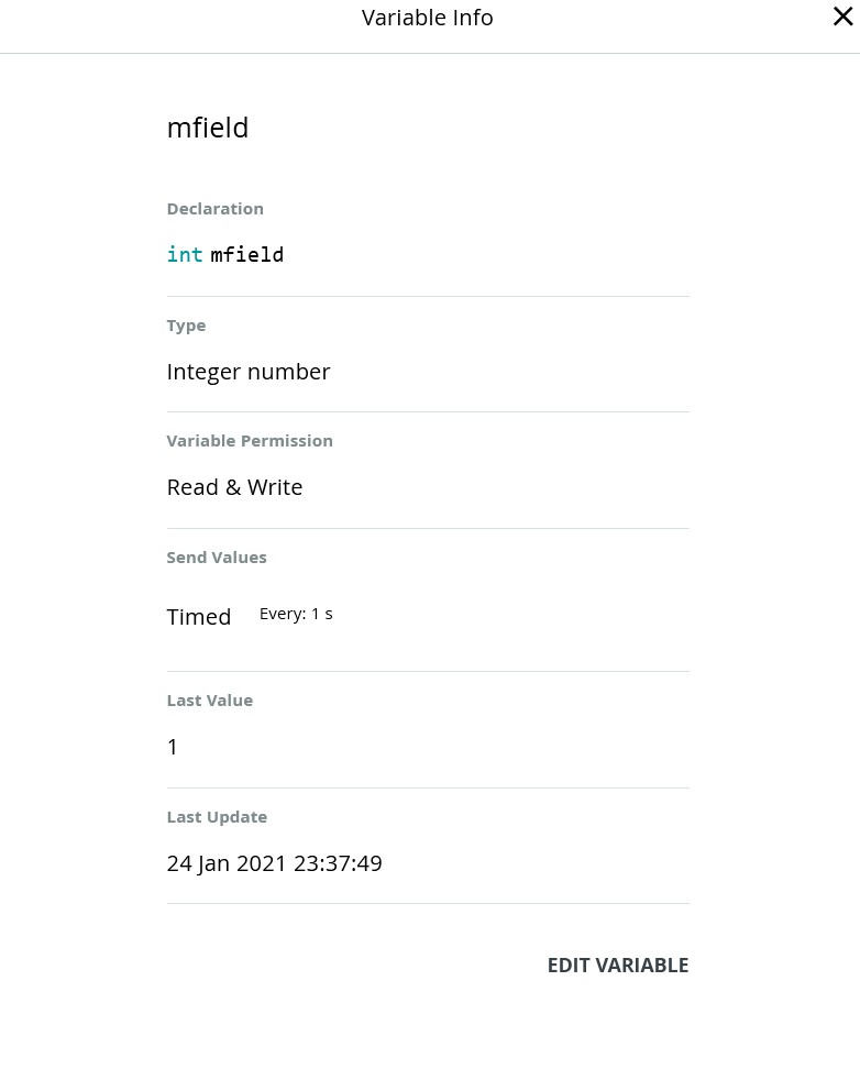
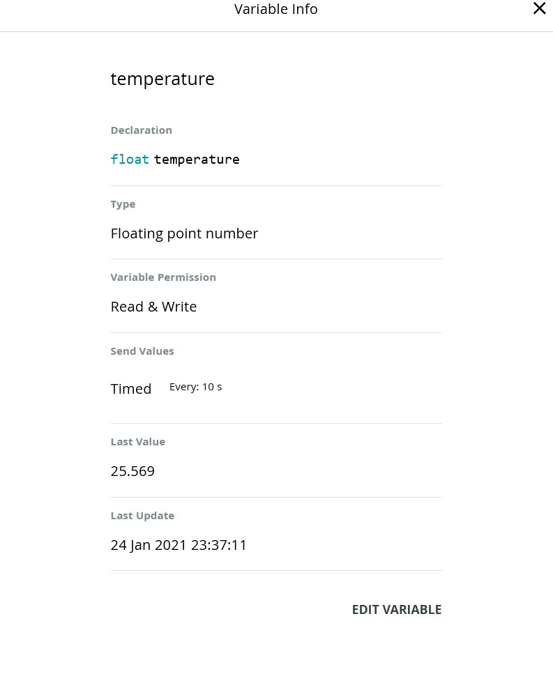
A detailed view of the variables setup follows. In addition to the C programming language variable type, the Arduino Create Variable definition provides variable permissions and a variable update policy.

Variable permissions are Read & Write, or Read Only. Read Only variables are output from the board. Read & Write variables can be modified by the board and in the cloud (i.e. used as an output from the board and input from the cloud).

The variable update policy is either On Change or Periodically. For the On Change option, a threshold is set to trigger when the variable changes. A function is added to the main sketch so that code can be executed when this change occurs. Example code for the On Event for the temperature variable is shown below.

void onTemperatureChange() {
  // Do something
}

For the Periodically option, a value for the time the event updates is set in seconds. Note that the event updates for these variables were set to 1 second, but the sketch uses a real time clock to sample the sensors at the start of every minute.

Magnetic Field Variable Configuration

The mfield variable is used to sample measurements of the magnetic field from the Grove Hall Sensor v1.0 that is connected to Digital Port 0 (D0). This sensor board contains a Hall effect device that switches on (logic low) when a south polarized magnetic field is perpendicular to the device and has field strength greater than a threshold value (BOP).

I purchased this sensor thinking that it could detect the magnetic field present in a AC power cable when current was flowing through the cable. It turns out that the magnetic threshold is too high to be useful for this application.

I would also investigate changing the sketch in the future to make mfield a Boolean variable type since the sensor only outputs on or off instead of a digital value. I would also change the variable permission to Read permission instead of Read & Write permission as the cloud would not change this variable with a UI switch or other cloud based user input.

Magnetic Field  Variable

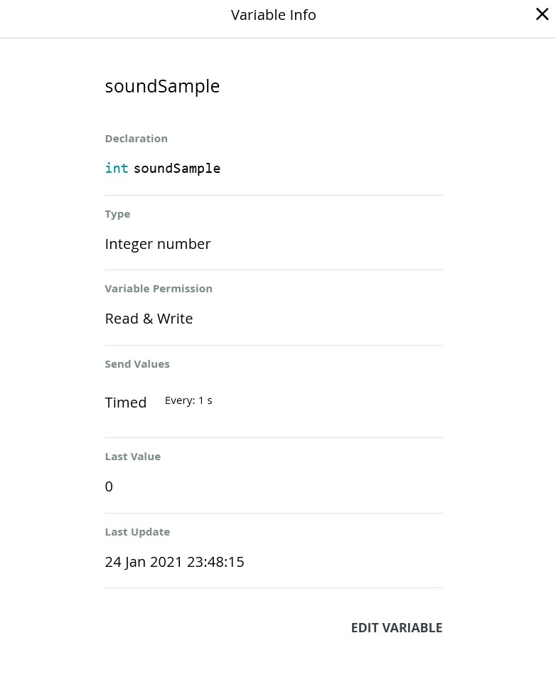
Sound Sample Variable Configuration

The soundSample variable is used to sample measurements from the Grove Sound Sensor V1.6 that is connected to Analog Input 1 (A1). The board contains an electret microphone and an LM358 op-amp amplifier that produces an analog output proportional to the sound level. An AnalogRead() on the MKR WiFi 1010 produces a reading with 12 bits of resolution. The variable permission could also be changed to a Read permission instead of Read & Write.

Sound Sample Variable

Temperature variable Configuration

The temperature variable is used to sample measurements from the Grove Temperature Sensor V1.2 that is connected to Analog Input 0 (A0). The board contains an Negative Temperature Coefficient (NTC) thermistor and an LM 358 op-amp to produce an analog voltage proportional to the temperature.

Temperature Variable

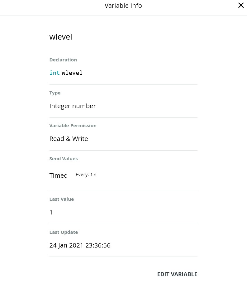
Water Level Variable Configuration

The wlavel variable is used to sample readings from the Grove Water Sensor v1.0 that is connected to Digital Input 1 (D1). The water sensor can indicate if it is dry or wet using a DigitaRead(). It has interdigitated traces providing a measure of conductivity. The conductivity structure is pulled up with a 1Meg ohm resistor. When the traces are dry, a DigitalRead() will be logic high. When the traces are wet, the water shorts traces to ground and a DigitalRead will be a logic low (0). This sketch here uses DigitalRead() to determine when the sensor is wet.

The Water Sensor could be moved to an Analog port and could be sampled with an AnalogRead(0) to get a range of wetness levels.

Water Level Variable

Sketch

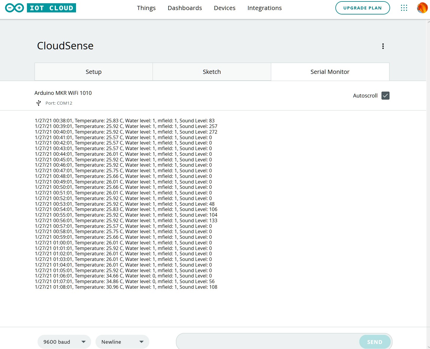
The sketch integrates all the sample code for each sensor with the code from the WiFi RTC tutorial, and samples each sensor sequentially every minute based on the real time clock. The sketch prints the time and value for sensor along with some text labels at the top of each minute to the serial monitor.

Serial Monitor

The figure below shows the output of the serial monitor when the program is running on the Cloud. To get a temperature change, I place my finger on the thermistor on the temperature sensor. I add a bit of water to the water sensor, and put a magnet near the Magnetic field sensor to get them to change values, but these changes were not captured in this figure.

Serial Monitor

Dashboard

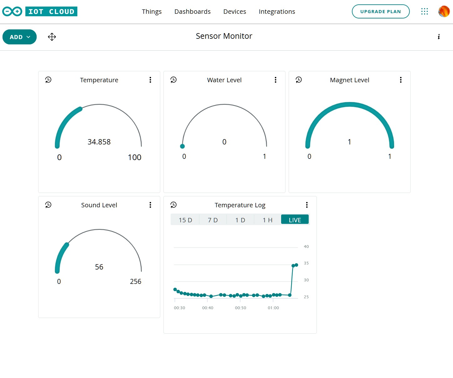
The dashboard was created by adding gauges to display the values of the temperature, wlevel, mfield, and soundSample variables. I also added a chart for the temperature variable to see the change over time.

The figure below shows the state of the sensors a short time after the sketch was started. A magnet was placed near the Hall sensor so it shows low, and the a drop of water was placed on the water sensor so it registers low. The Sound Sensor did not register a sound levels when this image was captured.

Dashboard 2

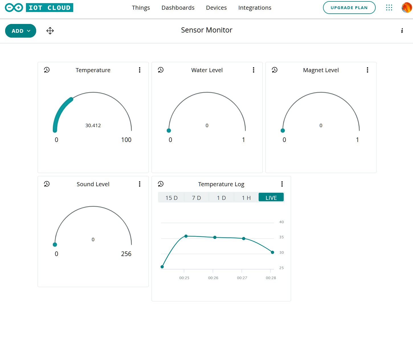
The figure below shows the status of the sensor after some time elapsed. A drop of water was placed on the water sensor so it registers a logic low. The magnet was too far away from the Hall sensor so it registers a logic high (no magnetic field above BOP), and the sound sensor picked up a sound level when this image was captured. The temperature log shows about 30 minutes of temperature samples. The log can be saved to a csv file.

Dashboard 2

CloudSense

CloudSense is the main sketch (C program).

/*
  Sketch generated by the Arduino IoT Cloud Thing "CloudSense"
  https://create.arduino.cc/cloud/things/<key-removed-for-security>

  Arduino IoT Cloud Variables description

  The following variables are automatically generated and updated when changes are made to the Thing

  float temperature;
  int wlevel;
  int mfield;
  int soundSample;

  Variables which are marked as READ/WRITE in the Cloud Thing will also have functions
  which are called when their values are changed from the Dashboard.
  These functions are generated with the Thing and added at the end of this sketch.
*/


#include "thingProperties.h"
#include <SPI.h>
#include <WiFiNINA.h>
#include <WiFiUdp.h>
#include <RTCZero.h>

/*
 *  Digital sensor pin definitions
 */
#define HALL_SENSOR 0
#define WATER_SENSOR 1
#define LED_01 2

/*
 * Analog sensor pin definitions
 */
#define pinTemp A0            // Define the pin to which the temperature sensor is connected.
#define pinSound A1           // Define the pins to which the sound sensor and LED are connected.

int keyIndex = 0;             // your network key Index number (needed only for WEP)
int status = WL_IDLE_STATUS;  // define a variable for the wifi status

WiFiSSLClient client;         // initialize the WiFi client library

/*
 * Define varialbles for calculationg local time for a given timezone.
 */
const int GMT = -5;           // change this to adapt it to your timezone
int diff = 0;                 // difference between gmt hours and GMT
int tz = 0;                   // hours correct for GMT time zone when GMT < 0
int tzhours = 0;              // used to hold the rtc.getHours value


/*
 * The following vairables are defined in thingProperties.h and
 * are generated automatically when you define a variable in
 * the setup. Defining them in the sketch will result in a
 * conflict.
 *
 * int mfield = 0;               // magnetic field read value
 * int wlevel = 0;               // water level read value
 * float temperature = 0;        // thermister temperature
 * int soundSample = 0;          // variable to hold the sound sample
 */

/*
 * Define variables for for the sensors
 */
const int B = 3975;           // thermister coefficient b-value
int tempVal = 0;              // thermister read value
float resistance = 0;         // thermister resistance
int soundVal = 0;             // sound lever read value
int soundThreshold = 4;       // sound level threahold value


/*
 * Define variables for the server
 */
char server[] = "www.arduino.cc";
bool sendRequest = true;      // used to understand if the http request must be sent

RTCZero rtcx;                  // create an RTC object


void setup() {
  // Initialize serial and wait for port to open:
  Serial.begin(9600);
  // This delay gives the chance to wait for a Serial Monitor without blocking if none is found
  delay(1500);

  // Defined in thingProperties.h
  initProperties();

  // Connect to Arduino IoT Cloud
  ArduinoCloud.begin(ArduinoIoTPreferredConnection);

  /*
     The following function allows you to obtain more information
     related to the state of network and IoT Cloud connection and errors
     the higher number the more granular information you’ll get.
     The default is 0 (only errors).
     Maximum is 4
 */
  setDebugMessageLevel(2);
  ArduinoCloud.printDebugInfo();

  pinMode(HALL_SENSOR, INPUT);
  pinMode(WATER_SENSOR, INPUT);
  pinMode(pinTemp, INPUT);
  pinMode(pinSound, INPUT);
  pinMode(LED_01,OUTPUT);

  checkWiFi();               // test to see that the WiFi module is working
  connectWiFi();             // connect to the wifi network and wait until it connects

  printWiFiStatus();        // print the status of the wifi network connection

/*
 * rtc was changed to rtcx so that it did on conflict with the ArduinoCloud setup
 */
  rtcx.begin();              // start the real time clock (RTC)

  getNTPtime();             // setup the RTC by getting the epoch from the NTP server
  enableRTCAlarm();         // stup the alarm to enable every minute
}


void loop() {
  ArduinoCloud.update();
  // Your code here
  //tempValx = temperature;
  if (sendRequest) {
    sendRequest = false;
    printDate();              // print the date as month, day, year
    printTime();              // print the time in hours, minutes, seconds for the timezone
    printTempSense();         // print the temperature
    printWaterSense();        // print the water sensor output 0=wet
    printMfieldSense();       // print the magnetic field sensor output 0=magnetic field
    printSoundSense();        // print the output of the sound sensor
    Serial.println();
    // httpRequest();
    // listenToClient();
  }
}

/*
 * Test the WiFi module works. Run once in setup()
 */
void checkWiFi() {

  if (WiFi.status() == WL_NO_SHIELD) {
    Serial.println("WiFi shield not present");

    // don't continue:

    while (true);
  }
}


/*
 *  Setup the wifi module by attempting to connect to WiFi network. Run once in setup()
 */
void connectWiFi() {

  while ( status != WL_CONNECTED) {

    Serial.print("Attempting to connect to SSID: ");
    Serial.println(SSID);

    // Connect to WPA/WPA2 network. Change this line if using open or WEP network:

    status = WiFi.begin(SSID, PASS);

    // wait 10 seconds for connection:

    delay(10000);
  }
}


/*
 * Setup the RTC by getting the time form the NTP. Run once in setup()
 */
void getNTPtime() {

  unsigned long epoch;
  int numberOfTries = 0, maxTries = 6;

  do {
    epoch = WiFi.getTime();
    numberOfTries++;
  }

  while ((epoch == 0) && (numberOfTries < maxTries));

  if (numberOfTries == maxTries) {
    Serial.print("NTP unreachable!!");
    while (1);
  } else {
    Serial.print("Epoch received: ");
    Serial.println(epoch);
    rtcx.setEpoch(epoch);
    Serial.println();
  }
}


 /*
  * Print the time
  */
void printTime() {

  tzhours = gmtHour(rtcx.getHours(), GMT);
  print2digits(tzhours);
  Serial.print(":");

  print2digits(rtcx.getMinutes());
  Serial.print(":");

  print2digits(rtcx.getSeconds());
}


/*
 * The original code to compute the time corrected for the users
 * timezone does not work for negatve GMT values. gmtHour() calculates
 * the correct hour assuming a 24 hour clock.
 */
int gmtHour(int hr, int gmt) {

  diff = (hr + gmt);
  if(diff < 0 ) {
    tz = (24 + diff);
  } else {
    tz = diff;
  }
  return tz;
}


/*
 * Print the date in month, day, year (mm/dd/yy) format
 */
void printDate() {

  Serial.print(rtcx.getMonth());
  Serial.print("/");

  Serial.print(rtcx.getDay());
  Serial.print("/");

  Serial.print(rtcx.getYear());
  Serial.print(" ");
}


/*
 * Print the WiFi status
 */
void printWiFiStatus() {

  // print the SSID of the network you're attached to:

  Serial.print("SSID: ");
  Serial.println(WiFi.SSID());

  // print your WiFi shield's IP address:

  IPAddress ip = WiFi.localIP();
  Serial.print("IP Address: ");
  Serial.println(ip);

  // print the received signal strength:

  long rssi = WiFi.RSSI();

  Serial.print("signal strength (RSSI):");
  Serial.print(rssi);
  Serial.println(" dBm");
}


/*
 * Print a number with two digits
 */
void print2digits(int number) {

  if (number < 10) {
    Serial.print("0");
  }

  Serial.print(number);
}

/*
 * Print the temperature
 */
void printTempSense() {
  // Print the temperature to the serial console.
  Serial.print(", Temperature: ");
  Serial.print(sampleTemp());
  Serial.print(" C, ");
 }

 /*
  * Print the water sensor state
  */
void printWaterSense() {
  Serial.print("Water level: ");
  Serial.print(sampleWlevel());
  }

  /*
   * Print the magnetic field sensor output 0=magnetic field present
   */
void printMfieldSense() {
  Serial.print(", mfield: ");
  Serial.print(sampleMfield());
}

/*
 * Print the sound level
 */
void printSoundSense() {
  Serial.print(", Sound Level: ");
  Serial.print(soundSample = sampleSound());
  setLED(soundSample, soundThreshold);
}

/*
 * Sample the temperature
 */
float sampleTemp() {
  // Read the temperature value
  tempVal = analogRead(pinTemp);

  // Determine the current resistance of the thermistor based on the sensor value.
  resistance = (float)(1023-tempVal)*10000/tempVal;

  // Calculate the temperature based on the resistance value in degrees Celsius.
  temperature = 1/(log(resistance/10000)/B+1/298.15)-273.15;
  return temperature;
}


/*
 * Sample the sound level
 */
int sampleSound() {
  //
  soundVal = analogRead(pinSound);
  return soundVal;
}


/*
 * Sample the magnetic field
 */
int sampleMfield() {
  // read magnetic field sensor
  mfield = digitalRead(HALL_SENSOR);
  return mfield;
}

/*
 * Sample the water sensor
 */
int sampleWlevel() {
  // read the water sensors
  wlevel = digitalRead(WATER_SENSOR);
  return wlevel;
}


/*
 * Turn the LED on if s > th
 */
void setLED(int s, int th) {
  if(s > th) {
    digitalWrite(LED_01, HIGH);
  } else {
    digitalWrite(LED_01,LOW);
  }
}


/*/
 * Set the alarm to enable every minute
 */
void  enableRTCAlarm() {
  rtcx.setAlarmTime(0, 0, 0);    //in this way the request is sent every minute at 0 seconds
  rtcx.enableAlarm(rtcx.MATCH_SS);
  rtcx.attachInterrupt(alarmMatch);
 }

/*
 * Enable the alarm
 */
 void alarmMatch() {
  sendRequest = true;
}

/*
 * this method makes a HTTP connection to the server:
 */
void httpRequest() {
  sendRequest = false;

  Serial.println();
  Serial.print("Request made @ ");
  printTime();
  int clientStatus = client.connect(server, 443);
  Serial.print(" status: ");
  Serial.print(clientStatus);
  Serial.println();

  if (client.connect(server, 443)) {

    // Make a HTTP request:

    //client.println("GET /asciilogo.txt HTTP/1.1");
    client.println("GET /search?q=arduino HTTP/1.1");
    client.println("Host: www.arduino.cc");
    client.println("Connection: close");
    client.println();
  } else {
    Serial.println("connection failed");
  }
}

void listenToClient(){
  unsigned long startTime = millis();
  bool received = false;
  while ((millis() - startTime < 5000) && !received) { //try to listen for 5 seconds
    while (client.available()) {
      received = true;
      char c = client.read();
      Serial.write(c);
    }
  }
  client.stop();
  Serial.println();
}

/*
 * The following functions were automatically defined by the variables
 * defined in the setup
 */

void onWlevelChange() {
  // Do something
}


void onTemperatureChange() {
  // Do something
}


void onMfieldChange() {
  // Do something
}


void onSoundSampleChange() {
  // Do something
}

thingProperties.h

thingProperties.h is automatically generated by the Arduino IoT Cloud, and contains the Variables defined in the Cloud Setup tab.

// Code generated by Arduino IoT Cloud, DO NOT EDIT.

#include <ArduinoIoTCloud.h>
#include <Arduino_ConnectionHandler.h>


const char THING_ID[] = "<key-removed-for-security";

const char SSID[]     = SECRET_SSID;    // Network SSID (name)
const char PASS[]     = SECRET_PASS;    // Network password (use for WPA, or use as key for WEP)

void onTemperatureChange();
void onWlevelChange();
void onMfieldChange();
void onSoundSampleChange();

float temperature;
int wlevel;
int mfield;
int soundSample;

void initProperties(){

  ArduinoCloud.setThingId(THING_ID);
  ArduinoCloud.addProperty(temperature, READWRITE, 10 * SECONDS, onTemperatureChange);
  ArduinoCloud.addProperty(wlevel, READWRITE, 1 * SECONDS, onWlevelChange);
  ArduinoCloud.addProperty(mfield, READWRITE, 1 * SECONDS, onMfieldChange);
  ArduinoCloud.addProperty(soundSample, READWRITE, 1 * SECONDS, onSoundSampleChange);

}

WiFiConnectionHandler ArduinoIoTPreferredConnection(SSID, PASS);

Secret

The Secret file contains the WiFi SSID and Password used by the sketch. This information does not get shared when you share your sketch with others.

SECRET_SSID <SSID-goes-here>
SECRET_PASS <PASS-goes-here>

References


Arduino WiFi 1010 with carrier board and Sensor Demo

morreale Monday 11 of January, 2021

Arduino MKR WiFi 1010

An Arduino MKR WiFi 1010 small board computer with a Grove sensor system compatible carrier board is proposed for controlling and monitoring the OpenAir Collective Direct Air Carbon Capture (DACC) Violet sorbent test prototype. The Violet DACC prototype will be used to evaluate the performance of sorbents to capture CO2 from the air and to determine the best geometry of the Violet design. The MKR WiFi 1010 has the following features:

  • SAMD21 Cortex-M0+ 32 bit microcontroller
  • u-block NIN-W102 radio module for Wifi and BLE
  • Powered by USB cable at 5V
  • Cryptochip
  • 8 digital pins
  • 13 PWM pins
  • 1 UART
  • 1 SPI
  • 1 I2C
  • 7 analog inputs
  • 1 analog output
  • 10 external interrupts
  • 256 KB flash memory
  • 32 KB SRAM
  • Small form factor

Arduino MKR Connector Carrier

The Arduino MKR Connector Carrier has connectors to connect to Grove compatible sensors. The carrier has the following features.

  • 5 Analog single Grove input ports
  • 1 Analog dual Grove input port
  • 5 Digital single Grove input ports
  • 1 Digital dual Grove input port
  • 1 I2C port
  • 1 UART port
  • 5V to 3.3V level translators
  • DC/DC converter (7 V to 16 V input to +5V and +3.3 V)

Grove Sensor Modules

Five Grove modules are attached to the MKR WiFi 1010 via the carrier board to demonstrate WiFi connectivity, and sampling sensors. This includes four sensors (temperature, water, sound, and Hall), and one LED socket module. The Grove system is made by Seeed Studio and is based on a four wire system (Power, Ground, and 2 signal pins). Pin spacing is 2 mm and has varying compatibility with STEMMA and Gravity connectors/modules.


No image specified. One of the following parameters must be set: fileId, randomGalleryId, fgalId, attId, id, or src.

This demonstration setup contains sensors the I had on hand and are attached in the following ports.

  • A0: Temperature Sensor
  • A1: Sound Sensor
  • D0: Hall Sensor
  • D1: Water Sensor
  • D2: LED Socket Module

The sensors set is to be replaced once the appropriate CO2, temperature, and pressure sensors have been finalized.

A number of sketch were written to capture sensor data, setup the MKR WiFi 1010 as a webserver and access point, and to demonstrate the Real Time Clock (RTC) that connects to a Network Time Protocol (NTP) service to set the time. These sketches were refined and combined to sample data with a time stamp for each series of sampled data. Samples are taken every 1 second in this demo sketch. A sample of some of the data is shown below.

Serial Monitor Output

SSID: Red2
IP Address: 192.168.1.134
signal strength (RSSI):-54 dBm
Epoch received: 1610340928

1/11/21 23:55:28, Temperature: 23.74 C, Water level: 1, mfield: 1, Sound Level: 16
1/11/21 23:55:29, Temperature: 23.74 C, Water level: 1, mfield: 1, Sound Level: 19
1/11/21 23:55:30, Temperature: 23.82 C, Water level: 1, mfield: 1, Sound Level: 3
1/11/21 23:55:31, Temperature: 23.82 C, Water level: 1, mfield: 1, Sound Level: 47

/* Data deleted. Water was placed on the water sensor
 * and my finger was held on the temperature sensor
 * to increase the temperature.
 */

1/11/21 23:56:55, Temperature: 23.91 C, Water level: 0, mfield: 1, Sound Level: 10
1/11/21 23:56:56, Temperature: 26.27 C, Water level: 0, mfield: 1, Sound Level: 5
1/11/21 23:56:57, Temperature: 25.39 C, Water level: 0, mfield: 1, Sound Level: 18
1/11/21 23:56:58, Temperature: 28.05 C, Water level: 0, mfield: 1, Sound Level: 15
1/11/21 23:56:59, Temperature: 29.32 C, Water level: 0, mfield: 1, Sound Level: 0
1/11/21 23:57:00, Temperature: 30.50 C, Water level: 0, mfield: 1, Sound Level: 14
1/11/21 23:57:01, Temperature: 30.96 C, Water level: 0, mfield: 1, Sound Level: 13
1/11/21 23:57:02, Temperature: 31.34 C, Water level: 0, mfield: 1, Sound Level: 48
1/11/21 23:57:03, Temperature: 31.62 C, Water level: 0, mfield: 1, Sound Level: 179
1/11/21 23:57:04, Temperature: 31.71 C, Water level: 0, mfield: 1, Sound Level: 46
1/11/21 23:57:05, Temperature: 31.99 C, Water level: 0, mfield: 1, Sound Level: 11
1/11/21 23:57:06, Temperature: 32.18 C, Water level: 0, mfield: 1, Sound Level: 15
1/11/21 23:57:07, Temperature: 31.52 C, Water level: 0, mfield: 1, Sound Level: 23
1/11/21 23:57:08, Temperature: 31.06 C, Water level: 0, mfield: 1, Sound Level: 17
1/11/21 23:57:09, Temperature: 30.60 C, Water level: 0, mfield: 1, Sound Level: 0
1/11/21 23:57:10, Temperature: 30.32 C, Water level: 0, mfield: 1, Sound Level: 27
1/11/21 23:57:11, Temperature: 29.86 C, Water level: 0, mfield: 1, Sound Level: 11
1/11/21 23:57:12, Temperature: 29.68 C, Water level: 0, mfield: 1, Sound Level: 12
1/11/21 23:57:13, Temperature: 29.50 C, Water level: 0, mfield: 1, Sound Level: 23
1/11/21 23:57:14, Temperature: 29.32 C, Water level: 0, mfield: 1, Sound Level: 26

This demonstration sketch shows that the MKR WiFi 1010 can be used to generate time stamped sensor data using the RTC and connect to the internet via WiFi. The next step is to connect it to the Arduino IoT Cloud so that the data can be monitored from anywhere.

The Sketch

The sketch is shown below.

/*
 * This sketch modifies the WiFi RTC tutorial found at
 * https://www.arduino.cc/en/Tutorial/WiFiRTC
 * to make it more module and to correct the hours output
 * when using negative GMT timezones.
 * By Jay Morreale
 * 1/10/2021
 *
 * MKR1000 - MKR WiFi 1010 - MKR VIDOR 4000 WiFi RTC
 * This sketch asks NTP for the Linux epoch and sets the
 * internal Arduino MKR1000's RTC accordingly.
 * created 08 Jan 2016
 * by Arturo Guadalupi <a.guadalupi@arduino.cc>
 * modified 26 Sept 2018
 * http://arduino.cc/en/Tutorial/WiFiRTC
 * This code is in the public domain.
 *
 */

#include <SPI.h>
#include <WiFiNINA.h>
#include <WiFiUdp.h>
#include <RTCZero.h>

#include "wifi_secrets.h";    // include the ssid and password

/*
 *  Digital sensor pin definitions
 */
#define HALL_SENSOR 0
#define WATER_SENSOR 1
#define LED_01 2

/*
 * Analog sensor pin definitions
 */
#define pinTemp A0     // Define the pin to which the temperature sensor is connected.
#define pinSound A1     // Define the pins to which the sound sensor and LED are connected.


RTCZero rtc;                  // create an RTC object

/*
 * Define WiFi variables
 */
char ssid[] = SECRET_SSID;    // your network SSID (name)
char pass[] = SECRET_PASS;    // your network password (use for WPA, or use as key for WEP)
int keyIndex = 0;             // your network key Index number (needed only for WEP)

int status = WL_IDLE_STATUS;  // define a variable for the wifi status

/*
 * Define varialbles for calculationg local time for a given timezone.
 */
const int GMT = -5;           // change this to adapt it to your timezone
int diff = 0;                 // difference between gmt hours and GMT
int tz = 0;                   // hours correct for GMT time zone when GMT < 0
int tzhours = 0;              // used to hold the rtc.getHours value

/*
 * Define variables for for the sensors
 */
int mfield = 0;         // magnetic field read value
int wlevel = 0;         // water level read value
const int B = 3975;     // thermister coefficient b-value
int tempVal = 0;        // thermister read value
float resistance = 0;   // thermister resistance
float temperature = 0;  // thermister temperature
int soundVal = 0;       // sound lever read value
int soundThreshold = 4; // sound level threahold value
int soundSample = 0;    // variable to hold the sound sample

/*
 * Setup
 */
void setup() {

  Serial.begin(115200);     // setup the serial monitor at the specified baud rate

  pinMode(HALL_SENSOR, INPUT);
  pinMode(WATER_SENSOR, INPUT);
  pinMode(pinTemp, INPUT);
  pinMode(pinSound, INPUT);
  pinMode(LED_01,OUTPUT);

  checkWiFi();               // test to see that the WiFi module is working
  connectWiFi();             // connect to the wifi network and wait until it connects

  printWiFiStatus();        // print the status of the wifi network connection

  rtc.begin();              // start the real time clock (RTC)
  getNTPtime();             // setup the RTC by getting the epoch from the NTP server
}

/*
 * Loop
 */
void loop() {

  printDate();              // print the date as month, day, year
  printTime();              // print the time in hours, minutes, seconds for the timezone
  printTempSense();         // print the temperature
  printWaterSense();        // print the water sensor output 0=wet
  printMfieldSense();       // print the magnetic field sensor output 0=magnetic field
  printSoundSense();        // print the output of the sound sensor
  Serial.println();

  delay(1000);              // wait a 1000 ms before getting the next time
}


/*
 * Function definitions
 */


/*
 * Test the WiFi module works. Run once in setup()
 */
void checkWiFi() {

  if (WiFi.status() == WL_NO_SHIELD) {
    Serial.println("WiFi shield not present");

    // don't continue:

    while (true);
  }
}


/*
 *  Setup the wifi module by attempting to connect to WiFi network. Run once in setup()
 */
void connectWiFi() {

  while ( status != WL_CONNECTED) {

    Serial.print("Attempting to connect to SSID: ");
    Serial.println(ssid);

    // Connect to WPA/WPA2 network. Change this line if using open or WEP network:

    status = WiFi.begin(ssid, pass);

    // wait 10 seconds for connection:

    delay(10000);
  }
}


/*
 * Setup the RTC by getting the time form the NTP. Run once in setup()
 */
void getNTPtime() {

  unsigned long epoch;
  int numberOfTries = 0, maxTries = 6;

  do {
    epoch = WiFi.getTime();
    numberOfTries++;
  }

  while ((epoch == 0) && (numberOfTries < maxTries));

  if (numberOfTries == maxTries) {
    Serial.print("NTP unreachable!!");
    while (1);
  } else {
    Serial.print("Epoch received: ");
    Serial.println(epoch);
    rtc.setEpoch(epoch);
    Serial.println();
  }
}


 /*
  * Print the time
  */
void printTime() {

  tzhours = gmtHour(rtc.getHours(), GMT);
  print2digits(tzhours);
  Serial.print(":");

  print2digits(rtc.getMinutes());
  Serial.print(":");

  print2digits(rtc.getSeconds());
}


/*
 * The original code to compute the time corrected for the users
 * timezone does not work for negatve GMT values. gmtHour() calculates
 * the correct hour assuming a 24 hour clock.
 */
int gmtHour(int hr, int gmt) {

  diff = (hr + gmt);
  if(diff < 0 ) {
    tz = (24 + diff);
  } else {
    tz = diff;
  }
  return tz;
}


/*
 * Print the date in month, day, year (mm/dd/yy) format
 */
void printDate() {

  Serial.print(rtc.getMonth());
  Serial.print("/");

  Serial.print(rtc.getDay());
  Serial.print("/");

  Serial.print(rtc.getYear());
  Serial.print(" ");
}


/*
 * Print the WiFi status
 */
void printWiFiStatus() {

  // print the SSID of the network you're attached to:

  Serial.print("SSID: ");
  Serial.println(WiFi.SSID());

  // print your WiFi shield's IP address:

  IPAddress ip = WiFi.localIP();
  Serial.print("IP Address: ");
  Serial.println(ip);

  // print the received signal strength:

  long rssi = WiFi.RSSI();

  Serial.print("signal strength (RSSI):");
  Serial.print(rssi);
  Serial.println(" dBm");
}


/*
 * Print a number with two digits
 */
void print2digits(int number) {

  if (number < 10) {
    Serial.print("0");
  }

  Serial.print(number);
}

/*
 * Print the temperature
 */
void printTempSense() {
  // Print the temperature to the serial console.
  Serial.print(", Temperature: ");
  Serial.print(sampleTemp());
  Serial.print(" C, ");
 }

 /*
  * Print the water sensor state
  */
void printWaterSense() {
  Serial.print("Water level: ");
  Serial.print(sampleWlevel());
  }

  /*
   * Print the magnetic field sensor output 0=magnetic field present
   */
void printMfieldSense() {
  Serial.print(", mfield: ");
  Serial.print(sampleMfield());
}

/*
 * Print the sound level
 */
void printSoundSense() {
  Serial.print(", Sound Level: ");
  Serial.print(soundSample = sampleSound());
  setLED(soundSample, soundThreshold);
}

/*
 * Sample the temperature
 */
float sampleTemp() {
  // Read the temperature value
  tempVal = analogRead(pinTemp);

  // Determine the current resistance of the thermistor based on the sensor value.
  resistance = (float)(1023-tempVal)*10000/tempVal;

  // Calculate the temperature based on the resistance value in degrees Celsius.
  temperature = 1/(log(resistance/10000)/B+1/298.15)-273.15;
  return temperature;
}


/*
 * Sample the sound level
 */
int sampleSound() {
  //
  soundVal = analogRead(pinSound);
  return soundVal;
}


/*
 * Sample the magnetic field
 */
int sampleMfield() {
  // read magnetic field sensor
  mfield = digitalRead(HALL_SENSOR);
  return mfield;
}

/*
 * Sample the water sensor
 */
int sampleWlevel() {
  // read the water sensors
  wlevel = digitalRead(WATER_SENSOR);
  return wlevel;
}


/*
 * Turn the LED on if s > th
 */
void setLED(int s, int th) {
  if(s > th) {
    digitalWrite(LED_01, HIGH);
  } else {
    digitalWrite(LED_01,LOW);
  }
}

References

The following Tutorials were used to create this sketch.


Hardware design resources

System Administrator Tuesday 29 of December, 2020

The IEEE has some fantastic webinars on circuits, devices, and power electronics to name a few. Many of the webinars are free and may require a little searching at the resource center to find them, otherwise try the YouTube channel if you are not a member. The list below is a selection of electronics related website that may be of interest in no particular order.


Smart TV Interconnection Guide

morreale Monday 28 of December, 2020

The Smart TV Interconnection guides shows how to connect a computer, laptop, or other device to a Smart TV with an High Definition Media Interface (HDMI). Devices may have one of the following interfaces or ports:

  • HDMI
  • Universal Serial Bus (USB) Type-C (USB-C)
  • DisplayPort
  • Digital Visual Interface (DVI)
  • Video Graphics Array (VGA)

A device with an HDMI port may be connected to a Smart TV with just a HDMI male to male cable. The gender refers the to gender of the connector. This is the simplest type of connection and is not shown in the guide.

A device with a USB Type-C, USB-C, or Thunderbolt port must use an USB-C male to HDMI female adapter plus a HDMI male-to-male cable. USB-C ports are most common on smart phones, tablets, and modern laptops.

A device with a DisplayPort must use an active DisplayPort male to HDMI female adapter and plus a HDMI male-to-male cable. DisplayPorts are common on computer docks, graphic cards, and some workstations. There is also a dual-mode DisplayPort that is labeled DP++. A DP++ port uses a passive DP++ male to HDMI female adapter and a HDMI male-to-male cable.

A device with a DVI port must use the appropriate DVI male to female HDMI adapter and a HDMI male-to-male cable. DVI ports have the following configurations: DVI-I (integrated) single-link and dual-link, and DVI-D (digital) single-link and dual link. DVI-I/D ports are most common on older graphics cards.

A device with a VGA port must use a VGA male to HDMI female adapter and a HDMI male-to-male cable. A VGA to HDMI adapter also has connections to the audio output port and a USB port to power the adapter. VGA ports a found on old computers and laptops.

Cables and adapters are available in a variety of performance grades and should be selected to match the highest capabilities of your device and Smart TV. The performance of the device and Smart TV can be found in the respective user manuals. The table in the guide provides the minimum level of performance for common resolutions with a 60 Hz refresh rate.


Hdmi Interconnects

Keysight Technologies RF Back to Basics Workship 2019

morreale Monday 28 of December, 2020

I attended the Keysight Technologies RF Back to Basics workshop in November 2019. The workshop was a very good review of RF analysis. I'd like to thank Walter Meissner for generating this list of useful links.

RF Presentations

KeySight - Find Presentations

S-parameter Application Notes

Articles & Papers

Testing and Calibration

Measurement Application Notes


Music Glove

morreale Sunday 26 of May, 2019
This YouTube video describes how to make a music glove based on the BBC Micro:bit. The Micro:bit can be programmed in Blocks, JavaScript, Python, and Scratch. The glove is sown together in real time with Alex Glow and Helen Leigh who designed the glove and teaches music technology. Alex and Helen discuss many topics while building glove and the links to some of these topics are shown below. I’m fascinated with the idea that the glove can be used create music by converting gestures and accelerometer data from the Micro:bit to MIDI commands that can control MIDI instruments.


Topics

The MINI.MU Music Glove

Image

@HelenLeigh on Twitter

Daphne Oram founded the BBC radiographic workshop and composed electronic music. She developed a technique for created music and it named after her – Oramics.

Image

Delia Derbyshire was a musician and electronic music composer at the radiographic workshop. She is known for creating the Doctor Who theme. The BBC released a documentary on the Sculptress of Sound: The Lost Works of Delia Derbyshire in 2010 and a short documentary The Delian Mode was released the year before.

Pure Data (or just Pd) is an open source visual programming language for multimedia.

Image

Matrix Voice is a voice development board used to create IoT voice apps. The board is compatible with the Raspberry Pi and more information about it can be found in The MagPi Matrix Voice Review article.

Image

SuperCollider is a platform for audio synthesis and algorithmic composition, used by musicians, artists, and researchers working with sound.

Image

The Sister Moon art project transmits voice and instruments at the moon and records the reflected signal. The project was developed by Marine Nicole Rojina and uses the Dwingeloo Radio Telescope in the Netherlands.

dadamachines Doppler is a new platform for open music hardware. It contains an ARM microprocessor and an Lattice ICE FPGA. Software can be developed using the Arduino IDE. A review of the board can be found at ycombinator.

Image

Teardown 2019 is a hacking, discovering, and sharing hardware event.

Vulpestruments has a blog that describes how to connect the music glove to a MIDI controller.

The Music Glove on Computerphile.

Drone development kit

morreale Friday 26 of August, 2016
Intel is working on the Aero Platform for Unmanned Aerial Vehicles (UAVs). It contains a quad core Atom processor, storage, IO, communications, flight controller, AirMap, and Intel's RealSense technology in package of about 2.5 × 3.5 inches (64 × 89 mm). The Aero platform is expected to cost $400, the vision accessory is $150, and the enclosure is $70, approximately. Yumeec is offering the Typhoon H drone for aerial photography incorporating the Aero platform and the RealSense vision system.

Image

High density 2 kW inverter webinar.

morreale Friday 27 of May, 2016
Professor Robert Pilawa-Podgurski from the University of Illinois gave a very good webinar on Tackling the Little Box Challenge - New circuit architectures to achieve a 216 W/in^3 power density 2 kW inverter.

The Little Box Challenge was a contest sponsored by Google and the IEEE to build an 2 kW 400 VDC to 240 VAC single phase inverter with at least a 50 W per cubic inch power density. The contest had a $1,000,000 prize. Over a hundred teams entered and eighteen teams were selected to submit their design for testing at NREL. Three teams passed the test. The webinar describes his teams efforts to build a inverter for the challenge.

Fundamentals of PCB Design

morreale Tuesday 17 of May, 2016
The Fundamentals of PCB Design webinar is given by Dr. Howard Johnson and is a wonderful overview of PCB design process. Dr. Johnson is the author of the very good book "High-Speed Digital Design: a Handbook of Black Magic".

2015 IEEE Proceedings

morreale Tuesday 09 of February, 2016
The 26th International Symposium on Space Terahertz Technology was held Match 16-18, 2015 in Cambridge MA. The proceeding of the symposium are available online. Session topics included:
  • System for Space Applications
  • Hot Electron Bolometers
  • Receivers
  • Bolometer Spectrometers
  • Sources
  • Instruments for CMB Observations
  • History & Current Developments
  • Detection Theory and Techniques
  • Direct Detectors
  • Posters

Image

Getting started with AWS IoT webinar

morreale Tuesday 09 of February, 2016
In case you missed it, the Getting started wit AWS IoT webinar is now available as an archive on YouTube as are the sildes. The webinar provide an overview of how to setup up and connect a device to the AWS cloud services. The webinar also demonstrate how to connect a pool pump to the cloud and have the cloud send SNS messages to a phone with the status of the pump.

It was pretty neat. The AWS IoT system uses certificates for authentication and authorization, and creates a shadow of the device in the cloud. All applications interact with the device shadow. When the device is in communications with the cloud via the MQTT had HTTP protocols using encrypted links with TLS 1.2, then it's state is synchronized with the shadow. There are SDK for devices running RTOS, and embedded Linux. The embedded Linux SDK is based on Node JS and supports Raspberry Pi, Adruino Yun, BeagleBone Green, Qualcomm Snapdragon DragonBoard, and other single board computer kits and devices.

Image

MD&M 2015 Philadelphia

morreale Monday 14 of September, 2015
The MD&M 2015 Philadelphia Conference and Expo is October 7-8, 2015 at the Pennsylvania Convention Center in Philadelphia, PA. I've been to the MD&M Expo at the Jacob Javits convention center in NYC. It was incredible for its size and scope. If the Philly Expo is anything like the NYC expo, then anyone thinking of building a product now or in the near future should attend at least one day. The NYC Expo is so large it took me 3 days of walking and talk to people to cover every isle in 2014. It was highly illuminating. This year it only took 2 days. Also, participating in the speed networking sessions was a lot fun too.